DIGITAL MODES INTERFACE
[HOME] [PROJECTS] [CONTACTS] [DOWNLOADS] [PICTURES]
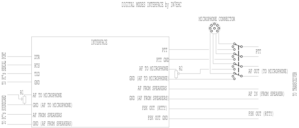
The use of an isolation interface between the radio
and the pc is higly recommended,in order to avoid the problems that could be
caused from ground loops.
When I first decided to build my own interface,I was
prepared to design and etch a simple PCB,instead I found the Crispino’s (I5XWW)
web site.
He sells a lot of electronic components and kits:one
of them is an excellent interface for the digimodes.
Since it was looking very functional and it was also
cheap,I decided to give it a try.
Few words about Crispino:
This interface was the first item of a bunch of stuff
I’ve later purchased from him.
Personally,I believe he’s one of the most serious and
honest sellers I’ve dealed with.
Once,I bought some electronic components from him,but
when I received the package I discovered that one part was broken,pretty sure
during transportation.
It took just an e-mail to Crispino,and two days later
I received another envelope with two new parts,free of charge.
It’s worth to check is site out
http://xoomer.virgilio.it/i5xww/interfaccia%20isolata.htm
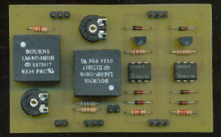
The interface can be assembled very quickly,and if you
don’t miss any solder joint,or install an active backwards component,it will
work right away.
As usual,as soon as I build a new project I start
looking if I can improve it in any way.
This is what I’ve done:
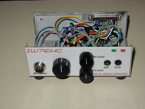
1)Every time that you want to switch from digital modes
to voice operation,you should unplug the (interface) microphone connector from
the radio and plug in the microphone connector.
After a while this can be pretty annoying.
To avoid this I’ve designed the circuit shown in the
schematic above.
The microphone is now plugged into the socket on the
interface,and the cable that comes out of it is plugged into the mic socket on
the radio.
This simple mod makes now very easy to choose between
digital or voice mode,by just flipping a knob of a rotary switch.
There is a intermediate position on the switch,that
kills all the PTT an AF signals going to the mic socket on the radio,useful if
you want to test a new software for the digital modes,but do not want to
activate the transmission on the radio.
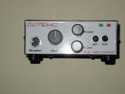
2)I’ve added two LED’s in series to the input circuits
from the serial port on the pc,in order to have a visual indication of the
status of the command signals.
The interface comes with two indipendent digital
outputs.
One goes to the PTT,I’ve used the second one to control
the FSK signal for the RTTY operations.
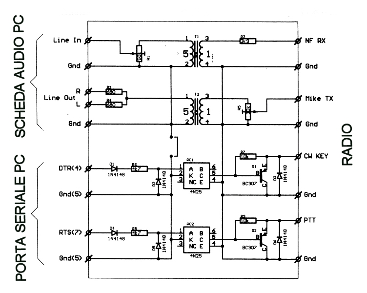
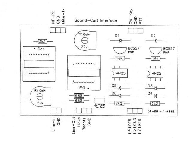
3)I’ve replaced the original trim-pots for the AF
levels (both IN and OUT) to and from the pc soundcard,with two linear
potentiometers of the same value.
Personally,I found very handy to have those two
controls available on the front panel,in order to be able to adjust them for
the correct level for each digital mode.
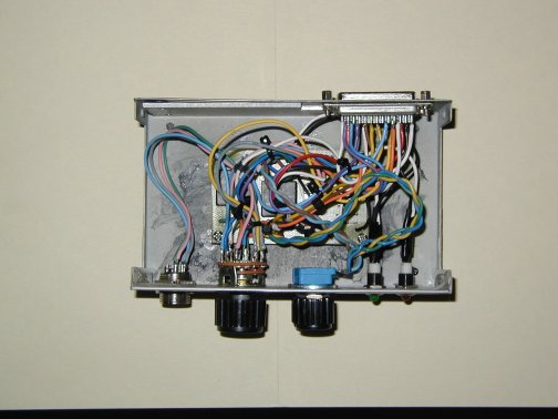
I’ve used a recycled enclosure,from an old parallel
ports switch.
To minimize RFI I’ve used some ferrite beads on the
wiring of the AF section.
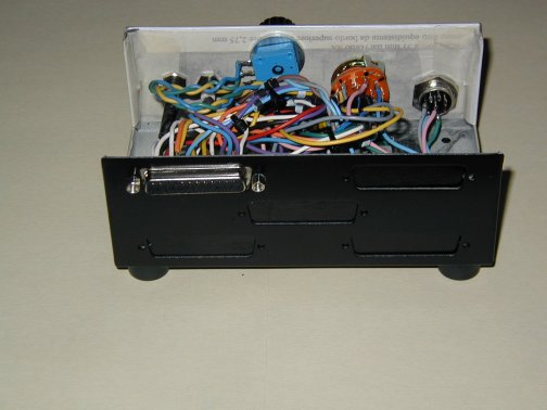
All the connections to/from the radio and the pc are
soldered on a DB25 25 pins socket.
This will give the user the option to use the same
interface on several rigs,what it takes is just a customized cable for each
rig.
[HOME] [PROJECTS] [CONTACTS] [DOWNLOADS] [PICTURES]
![]()
Copyright 2007 by IW7EHC all rights reserved
