)
DOUBLE DIGIMODES INTERFACE
AND PATCHBOX
[HOME] [PROJECTS] [CONTACTS] [DOWNLOADS] [PICTURES]
download the schematic in high resolution
I designed this interface back in 2006,looking for a solution that would allow me to speed up the phone to digimodes (and viceversa) changes,on several radios.
The project consists of two identical interfaces for digital modes,with an additional switching circuit,that allows to operate two separate radios both in phone and digimodes,from the same computer,just by making selections on few rotary switches.
This will simplify and speed up the modes changes,since it will be no longer required to unplug and switch connectors and jacks.
All it takes is the proper positioning of 4 rotary switches.
More specifically:
AF SOURCE 1 SWITCH (phone\digital mode selection for Radio1\interface1)
2 positions rotary switch:
The AF signal generated from the pc's soundcard is sent to the microphone input of the radio 1.
The microphone plugged in the 8 pin socket (onboard the interface) is connected to the microphone connector plugged in the radio 1.
AF SOURCE 2 SWITCH (phone\digital mode selection for Radio2\interface2)
2 positions rotary switch:
The AF signal generated from the pc's soundcard is sent to the microphone input of the radio 2.
The microphone plugged in the 8 pin socket (onboard the interface) is connected to the microphone connector plugged in the radio 2.
SERIAL LINK SWITCH (serial link selection)
3 positions rotary switch
The pc's serial port is connected to the interface 1.
Intermediate position,where the pc's serial port is left disconnected from both interfaces (useful to prevent accidental activations of PTT).
The pc's serial port is connected to the interface 2.
AF OUT SWITCH (AF generated from the soundcard selection)
4 positions rotary switch
The AF from the pc's soundcard is sent to the jack on the interface front panel,for a connection to an headphone.
The AF from the pc's soundcard is sent to the jack on the back panel of the interface,for a connection to some external speakers.
The AF from the pc's soundcard is sent to the AF input of the interface 2,to be sent to the AF input (MIC) of the radio connected to the interface 2.
The AF from the pc's soundcard is sent to the AF input of the interface 1,to be sent to the AF input (MIC) of the radio connected to the interface 1.
I've shown on a table all the possible combinations (an empty cell means that for that specific operating mode the relevant switch is not used,and therefore the position of it is non influential)
OPERATING MODE |
AF SOURCE 1 |
AF SOURCE 2 |
SERIAL LINK |
AF OUT |
|
digital modes with Radio 1 |
PC TO RADIO |
INTERFACE 1 |
INTERFACE 1 |
|
|
phone with Radio 1 |
MIC TO MIC |
|
0 |
|
|
digital modes with Radio 2 |
|
PC TO RADIO |
INTERFACE 2 |
INTERFACE 2 |
|
phone with Radio 2 |
|
MIC TO MIC |
0 |
|
|
no interface in use |
|
|
0 |
|
|
audio from pc to headphones |
|
|
0 |
HEADPHONES |
|
audio from pc to speakers |
|
|
0 |
SPEAKERS |
CONSTRUCTION TIPS
FRONT AND BACK PANELS
In order to avoid ground loops through the several AF connectors,the front and back panels of the enclosure must be done with an isolating material (plastic,plexiglass,....),of the proper thickness,to avoid bending.
ROTARY SWITCHES FEATURES
AF SOURCE 1 SWITCH : 4 ways 2 positions
AF SOURCE 2 SWITCH: 4 ways 2 positions
SERIAL LINK SWITCH: 3 ways 3 positions
AF OUT SWITCH: 4 ways 4 positions
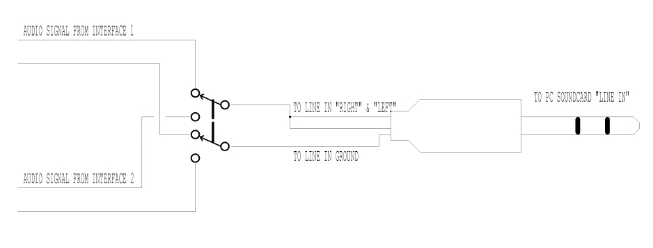
"LINE IN" JACK CONNECTION
The AF signal from the radios,must be sent to the pc's soundcard,through the "LINE IN" input.
Since there is the need to tie in the same jack the two signals from the the two interfaces,a solution could be this:
the AF coming from the interface 1 is wired on the RIGHT channel of the LINE-IN jack,and
the AF coming from the interface 2 is wired on the LEFT channel of the LINE-IN jack.
Since those two signals are coming from the output of the isolation trasformers,there should be no potential loops issues.
As an alternative,an additional double switch could be wired in,to select only the output of the interface in use,and wiring the LINE-IN jack as shown in the image below.
WHAT INTERFACE TO USE?
I'm not showing any interface schematic on purpose.
Any isolated interface (isolated on both the digital and audio sides) can be used.
Some little customization of the connections may be required,in order to suit the needs of the user.
[HOME] [PROJECTS] [CONTACTS] [DOWNLOADS] [PICTURES]
![]()
Copyright 2007 by IW7EHC all rights reserved
