END FED HALF WAVE ANTENNA (EFHWA)
[HOME] [PROJECTS] [CONTACTS] [DOWNLOADS] [PICTURES]
[<< to the page 1 of the EFHWA antenna ]
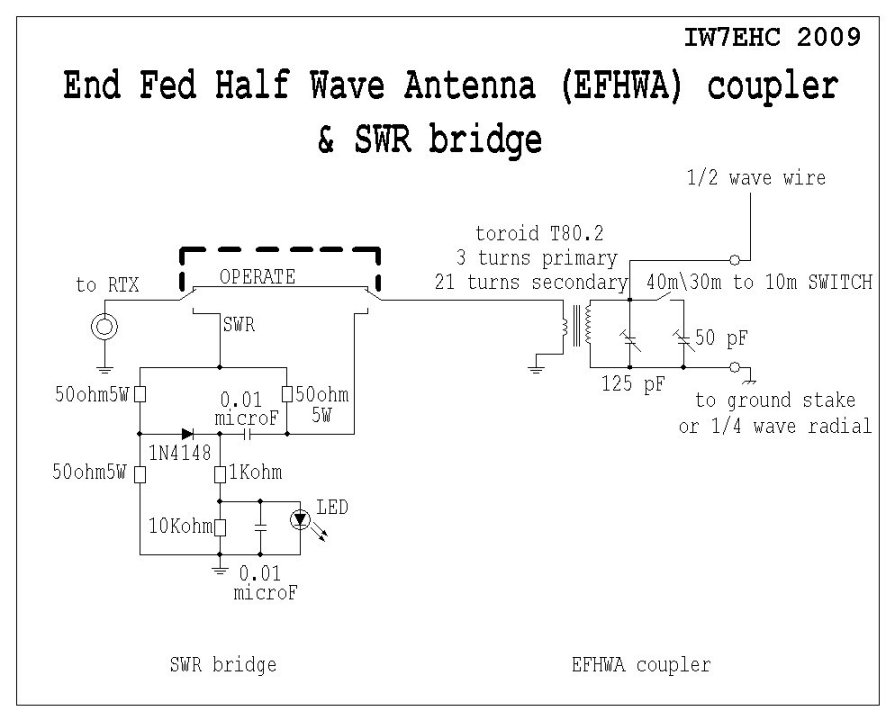
As shown in the schematic,the LC network is coupled with an SWR bridge meter,an easy way to tune the main circuit without an external SWR measuring device.
When the switch is in the position "SWR",the primary of the transformer becomes the fourth leg of the bridge (the other three legs are the 50 ohm,5 Watt resistors).
Once the LC network is tuned,the resistive impedance seen across the primary winding of the transformer will be 50 ohm,or a value close to it,and this will balance the bridge:
there will be no current flowing between the left and right legs of the bridge (through the diode 1N4148 and the 0,01 microF capacitor),and the LED will be off.
So,all is needed to do to tune the circuit is to rotate the knob for minimum illumination of the LED.
Then the switch can be flipped back to OPERATE,this will exclude the bridge and connect the primary of the transformer directly to the antenna socket of the transceiver.
I would recommend to choose a transparent case LED,as this will make easier to detect any little variations in brightness,when tuning.
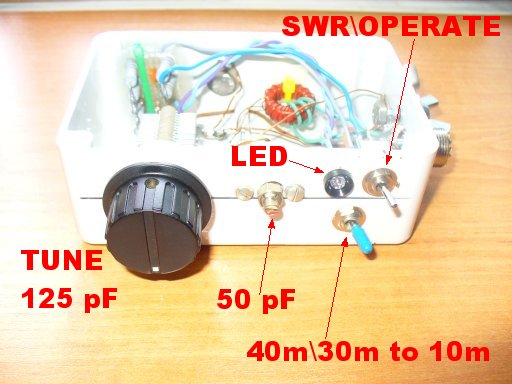
The 50 pF capacity (that goes in parallel with the 125 pF to tune in the 40 meters band) is a capacitive trimmer,adjusted in the fully meshed position.

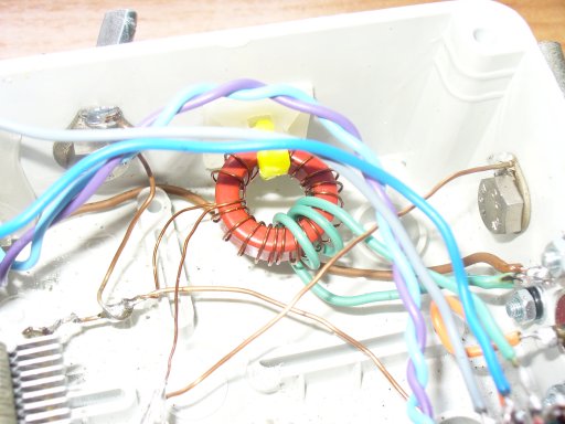
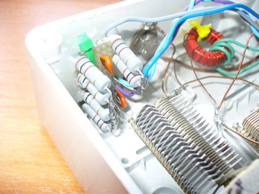
Detail of the transformer
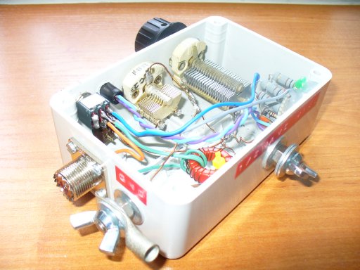
Detail of the SWR bridge,note the 3 pairs of 100 ohm resistors,connected in parallel,in order to have 3 resistors of 50 ohm each,and increase the power handling ability of the bridge.
The bridge is rated QRP,so it can't be used with more than 5 Watts,but it will be possible to tune with few Watts,and then bypass it (switch to OPERATE) and increase the power.
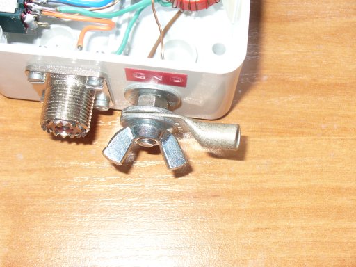
Detail of the connections to the radiating wires.
The picture shows the ground connection,but the same system is used to connect the 1\2 wave wire:
the lug is sandwiched between two flat washers and held in position with a wingnut.
It's preferable to solder the wires to the lug,even if the one shown in the picture is a crimp-on model.
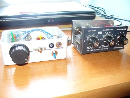
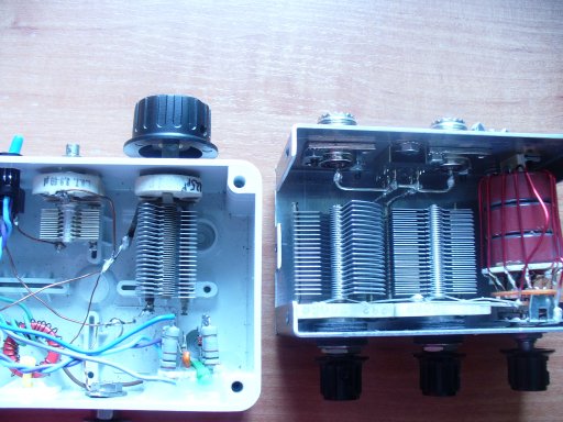
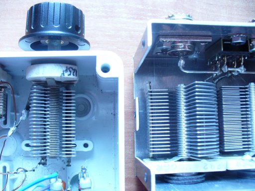
Comparison with the tuner MFJ-902:
the gap between the plates of the variables is the same,it should be possible to use this tuner with power levels a bit higher than QRP.
 [<< to the page 1 of the EFHWA antenna ]
[HOME] [PROJECTS] [CONTACTS] [DOWNLOADS] [PICTURES]
![]()
Copyright 2007 by IW7EHC all rights reserved
