 [ to the page 2 of the EFHWA antenna >>]
END FED HALF WAVE ANTENNA (EFHWA)
[HOME] [PROJECTS] [CONTACTS] [DOWNLOADS] [PICTURES]
[ to the page 2 of the EFHWA antenna >>]
In my opinion,this antenna is the best solution for portable operations:
a single wire,cut at 1\2 wavelength of the desired frequency,fed at one end,therefore without center isolators and coax cable to make it heavy and bulky.
Easy to deploy,it can be tossed on the branches of a tree,pulled in horizontal between two supports,or vertical with a fishing rod (10 meters= 1\2 wave in 14MHz,for lower frequencies - longer wires - the fishing rod can be used to hold the first section of the wire,that can be later bent - horizontally - in the last section)
Another important detail,if a good ground connection is available,there is no need for radials,all you need is a short wire connected to a stake in the ground.
As an option to the ground stake,a single 1\4 wave radial can be used.
The impedance seen at the end (in our case the feed point) of a 1\2 wavelength wire is few thousands ohm (Kohm),leading to the conclusion that a coupler will be required to match the impedance levels of the two systems, the antenna (Kohm) and the radio (50 ohm).
For this purpose an LC parallel network can be used.
It can be assembled in many different ways,with L (fixed or variable) air or core wound,and C variable.
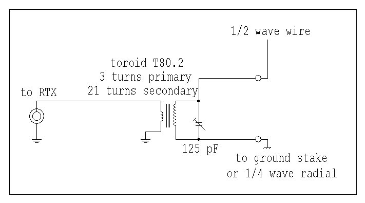
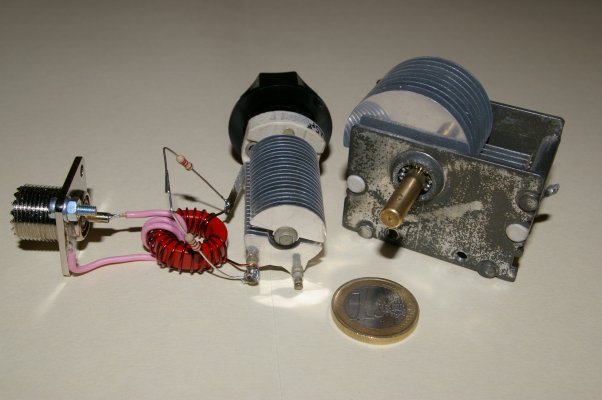
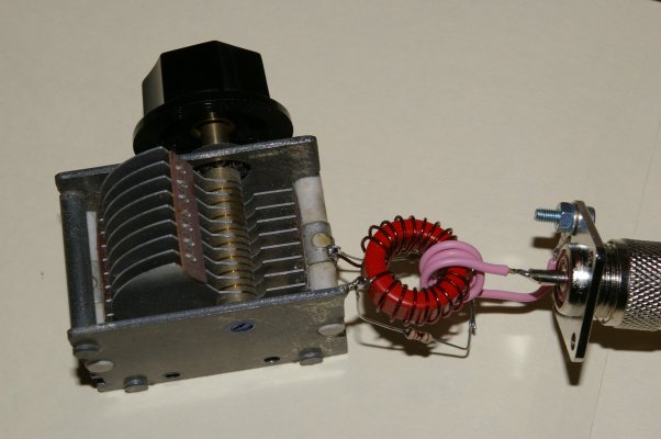
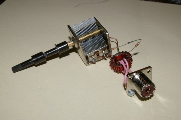
To make the assembling process easy I choose to keep L fixed (core wound) and C variable,as shown in the following schematic
A visit to AA5TB's web site turned out to be a big source of ideas and useful tips.
The site explains how it can be possible to choose different ratios on the transformer windings,based on the value of inductance ( L ) needed at the secondary of the transformer to make the LC network resonant at the desired frequency.
To each ratio will correspond a specific impedance,of a known value.
In my case I used the 7:1 ratio (seen from the high impedance side,21 turns on the secondary and 3 turns on the primary),that should take the resistive impedance of the antenna to a value close to 2500 ohm (2,5 Kohm).
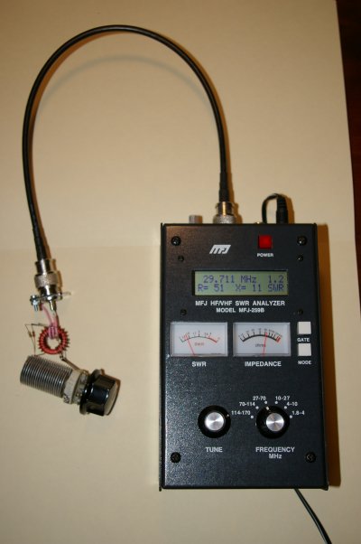
After building the LC circuit,I hooked up two resistors in series (2200+220=2420 ohm) across the variable capacitor,simulating the resistive load of a resonating antenna.
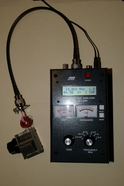
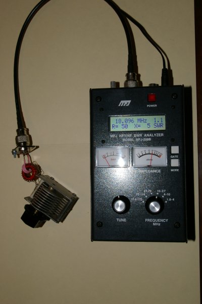
I took some readings with the antenna analyzer MFJ-259B,shown in the table below
|
FREQUENCY (MHz) |
R (ohm) |
X (ohm) |
SWR |
|
1,8 |
> |
> |
> |
|
3,5 |
> |
> |
> |
|
7 |
> |
> |
> |
|
10,100 |
51 |
7 |
1,1 |
|
10,150 |
50 |
4 |
1,0 |
|
14,000 |
54 |
11 |
1,2 |
|
14,350 |
53 |
7 |
1,1 |
|
18,068 |
52 |
6 |
1,1 |
|
18,168 |
49 |
4 |
1,0 |
|
21,000 |
54 |
9 |
1,2 |
|
21,450 |
52 |
7 |
1,1 |
|
24,890 |
55 |
9 |
1,2 |
|
24,990 |
54 |
8 |
1,1 |
|
28,000 |
57 |
14 |
1,3 |
|
29,700 |
50 |
10 |
1,2 |
As shown,the use of a transformer with a ratio of 7:1 and a capacitor of 125 pF gives a continuous coverage of all the bands from 30 to 10 meters.
In the remaining bands (160,80 and 40 meters) the match was very difficult,and I was never able to get some acceptable readings of R and X.
It was clear that the value of the components of the LC network wasn't adeguate for the low bands.
Since I wanted to build a tuner that would allow me to operate from 40 to 10 meters,I carried out few more tests,using different variable capacitors,keeping the same transformer used before.
All the tests gave the same result:
Keeping the same transformer (3 turns on the primary,21 turns on the secondary,wound on a toroid T80.2),any capacitor with a value higher than 125 pF didn't improved at all the match on the 40 meters band,jeopardizing at the same time the match on the higher bands ( 15m,12m,10m ),that was possible with the 125 pF capacitor.
At this point it was clear that,in order to get more bandwidth I could have built a new transformer with some intermediate taps on the secondary winding,and switch between them according to the frequency,but in this case I would've had to operate on two separate knobs (the variabile capacitor and the switch on the secondary of the transformer).
There was another option,keep the 7:1 transformer and the 125 pF variable,and add a second capacitor in parallel, together with a switch,as shown in the following picture
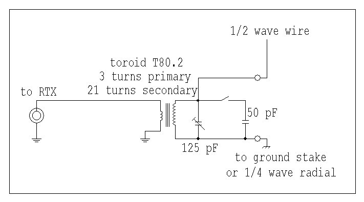
With this new circuit it would now be possible to tune on all the bands from 40 to 10 meters:
from 30 to 10 meters bands the switch is open,the capacity in use is 125 pF
in the 40 meters band the switch is closed,the capacity in use is 175 pF (125+50 pF)
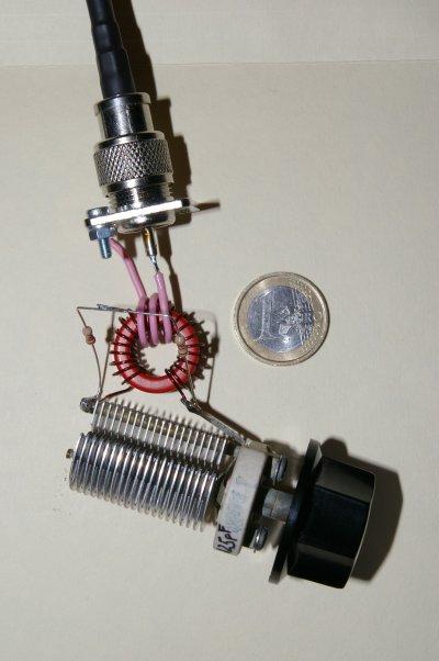
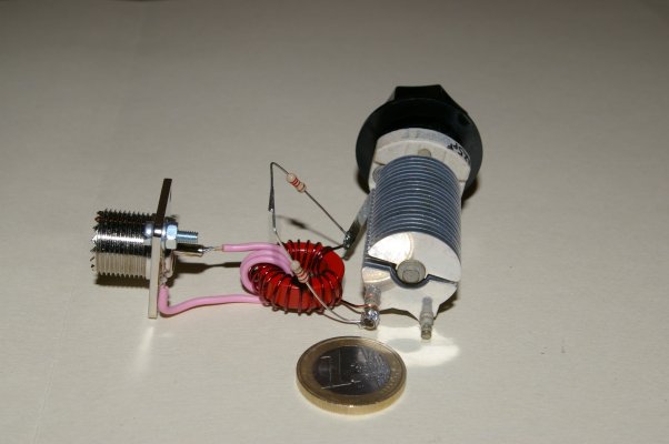
The next page is showing the construction details of the tuner
[ to the page 2 of the EFHWA antenna >>]
[HOME] [PROJECTS] [CONTACTS] [DOWNLOADS] [PICTURES]
![]()
Copyright 2007 by IW7EHC all rights reserved
