15/20/40m WIRE DIPOLE "UN7JOT"
[HOME] [PROJECTS] [CONTACTS] [DOWNLOADS] [PICTURES]
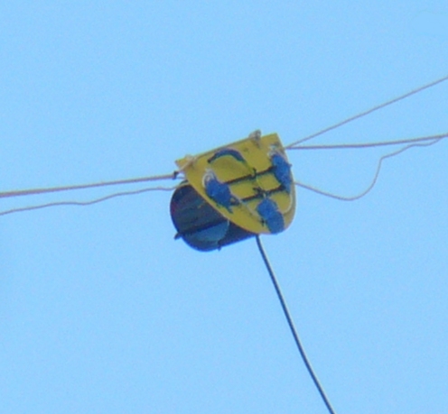
Detail of the center insulator,note the strain relief rope,that runs for all the lenght of the antenna,tied to the end insulators and to the insulator itself (on two points,as shown in the picture)
This will relief the strain from the copper wires.
It's also visible the RTV sealant (the 4 blue spots),used to waterproof the connections,in the areas potentially exposed to moisture or rain.
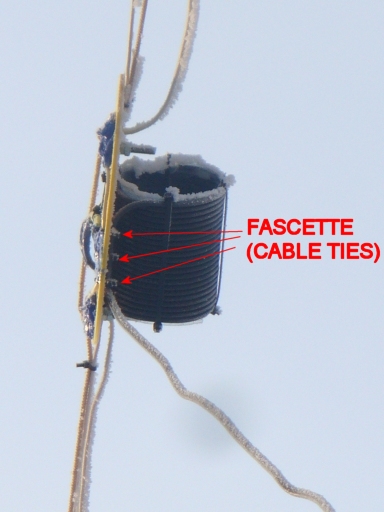
View of the cable ties used to hold the coax cable to the center insulator.This detail it's very important to avoid stressing the coax section that goes to the station.
Sharp bends of the cable should be avoided at all times.
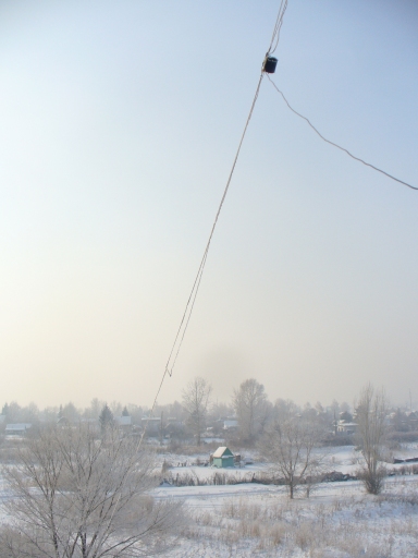
This picture shows the slope that was given to the dipole.
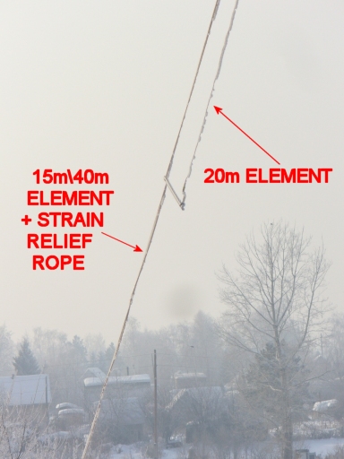
Detail of the end spacer for the 20m element.
Note the strain relief rope together with the 40m wire.
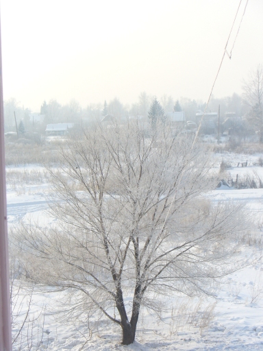
The tree that was used to secure the lower section of the dipole [<<PAGE 1] [<<PAGE 2]
[HOME] [PROJECTS] [CONTACTS] [DOWNLOADS] [PICTURES]
![]()
Copyright 2007 by IW7EHC all rights reserved
