15/20/40m WIRE DIPOLE "UN7JOT"
[HOME] [PROJECTS] [CONTACTS] [DOWNLOADS] [PICTURES]
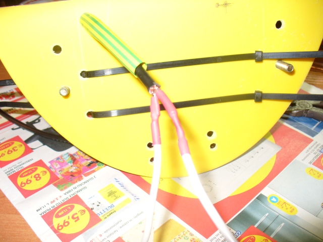
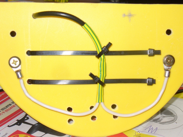
In this picture are visible the cable ties (the 2 horizontal ones) who are used to keep the choke in position on the center insulator.
The choke is on the opposite side of if.
It's also visible the splice between the coax cable (coming from one end of the choke) and the two wires who will be hooked up to the dipole elements.
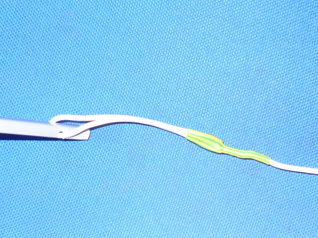
Detail of the two wires who will be hooked up to the dipole elements.
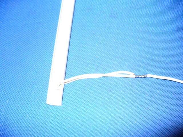
Detail of the system used to secure the terminal section of the 20m element to the plastic insulator\spacer.
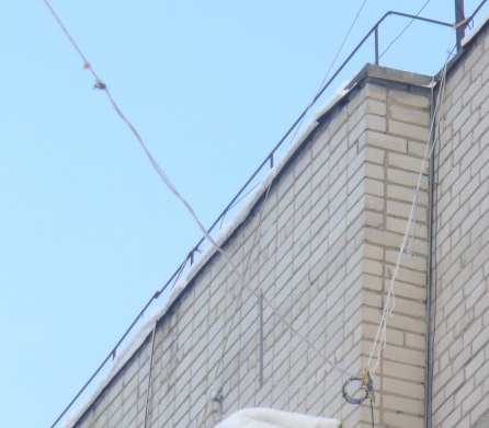
The dipole in position.The tele-lens gives the impression that the antenna is very close to the wall,but in the following pictures it will be clearly visible the real orientation of the antenna.
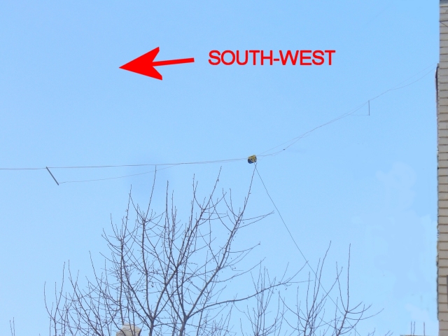
I decided to install the dipole with some slope.
In this type of configuration,the coax inner conductor must be connected to the top element (the one on the right,in the picture).
In the first version I built,I used only one single spacer between the two elements,installed at the end of the 20m arm.
It's recommended to use at least 4 spacers for each side,this will prevent the wires from twisting. [<<PAGE 1] [PAGE 3>>]
[HOME] [PROJECTS] [CONTACTS] [DOWNLOADS] [PICTURES]
![]()
Copyright 2007 by IW7EHC all rights reserved
