BAND SELECT CARD FOR ICOM RADIOS
[HOME] [PROJECTS] [CONTACTS] [DOWNLOADS] [PICTURES]
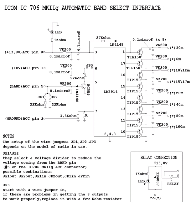
This card,that connects to an ICOM HF radio through the ACC connector,will drive 8 outputs,one for each specific band (6 m,10 e 12 m,15 e 17 m,20 m,30 m,40 m,80 m,160 m). Those outputs can then be used to drive coax relays,in order to automatically select the proper antenna for the proper band.The original project is from Bob K6XX. Lately Pasquale IW0HEX implemented some changes on it.The PCB I've designed is based on both versions.
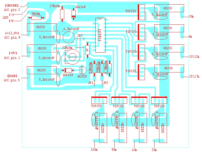
The value of the resistor between the pin 7 of the LM3914 and ground is 3,3 Kohm.The value of this resistor determines the amount of current that will drive the 8 Darlington transistors.In case different transistors are used as output devices,there is the possibility to install a second resistor,in parallel with the 3,3K one,in the pads marked "R".
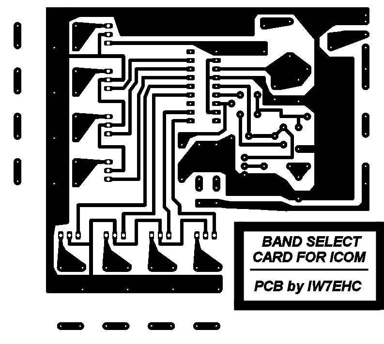
There are 4 wire jumpers,as shown in the components layout picture.The jumper at the left of the resistor R is required to solve a tracks crossing,while the other 3 have more specific functions:
JP1 and JP2 will define the resistance value of a voltage divider,that could be required if the voltage at the BAND pin of the radio is not the proper one.The options are:
no voltage divider JP1 and JP2 out
22 Kohm divider JP1 in
11 Kohm divider JP1 and JP2 in
The JP3 jumper must be in.It should be removed and replaced with a 4,7 Kohm only if adjusting the 22 Kohm pot will not be enough to trigger the outputs properly.
[HOME] [PROJECTS] [CONTACTS] [DOWNLOADS] [PICTURES]
![]()
Copyright 2007 by IW7EHC all rights reserved
