TRANSISTORIZED CW BUG
[HOME] [PROJECTS] [CONTACTS] [DOWNLOADS] [PICTURES]
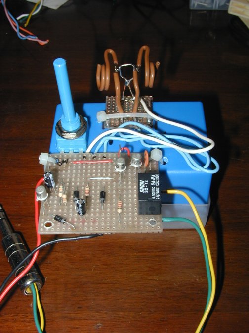
It’s a very simple circuit,I’ve assembled several
versions of it for the various rigs I’ve been building.
It can be considered as an electronic version of the
semiautomatic bug: like the Vibroplex the dahs do not self-complete,and you get
a steady stream of dits as long as you keep the dit pad down.
The author is Todd
VE7BPO,and the original article can be found at
http://www.qrp.pops.net/multivibrator.asp
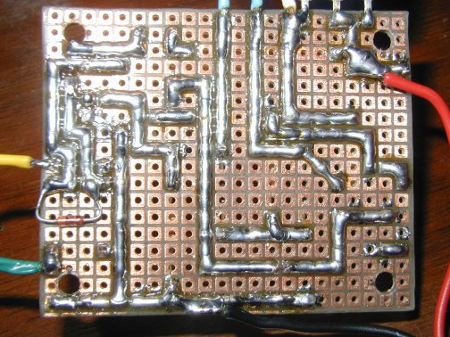
I’ve only designed a PCB for it.
Below is the article from Todd’s site:
Simple Electronic Keyer
A simple keyer suitable for a popcorn QRP transmitter
can be built around an astable multivibrator and an example of such is shown
above. The basic design of this keyer is from notes, however the original
author of the circuit is unknown. The notes were written in 1973 . I modernized
the circuit, added a variable speed control and designed an additional output
driver stage.
Keyer Operation
Keying this circuit generates either dits and spaces or dahs and spaces. When
the keyer is idle, Q1 is on and Q2 and Q3 are switched off. When the user sends
code, Q1 turns off and Q2 and Q3 switch on and in turn key any device
appropriately connected to the collector of Q3. The off-time of Q1 sets the
on-time of Q2 and Q3. The off-time of Q2 and Q3 is set by the 22K Q2 base
resistor. This off-time is the set time of the spaces and is constant.
The 68K resistor on the base of Q1 is about three times the resistance of the
22K base resistor on Q2 and consequently dahs are ~ three times the length in
duration than dits. Spaces and dits are of the same length of time because when
sending dits, the 68K base resistor is parallelled with the 33K resistor and
effectively the resistance is ~22K ohms. If the optional relay driver
transistor Q4 is used instead of Q3, the theory is the same, just substitute Q4
wherever you see Q3.
Keyer Speed
The keyer speed is very sensitive to the power supply voltage and any keyer
speeds mentioned are ball-park values. Your results may vary depending on your
VCC and component tolerances. If the 25K speed control pot is turned to minimum
resistance, the actual power supply voltage will be present on both the paddle
common and the top end of the 68K base resistor. This will be the maximum speed
for the keyer. In fact, the speed control pot could be omitted if you want to
economize and the keyer will run at the maximum speed as determined by C1 and
C2. If you do not want the speed control feature, connect the paddle common and
the 68K resistor to the VCC supply. Another alternative is to build a two speed
keyer by using a switch to switch in or out a fixed resistor to vary the
voltage instead of using a potentiometer. A trimmer resistor may also be used
for "lid-off" speed adjustments.
Varying the base-bias voltage with a pot changes the charging rate on
capacitors C1 and C2. Although, I experienced no problems be careful with some
resistances/VCCs as the circuit may be unable to provide enough current to
saturate the transistors when the base-bias voltage is at its minimum setting (
pot set to maximum resistance ). Smaller pots such as 10K can also be used with
a more limited ability to reduce the keyer speed below the maximum rate.
To set the maximum rate for the keyer, it is necessary to vary the value of C1
and C2.
FOR THIS CIRCUIT TO FUNCTION CORRECTLY C1 MUST EQUAL C2
An experiment was conducted with the 25K pot removed and the paddle common and
the supply end of the 68K resistor connected to the main B+ terminal. VCC was
measured at 13.8 volts. C1 = C2.
The words per minute were counted for four different standard capacitance
values and the results were as follows:
2.2 uF = 27 WPM
3.3 uF = 23 WPM
4.7 uF = 17 WPM
10 uF = 9 WPM
For this project, I settled with the 3.3 uF value, although personally, I use a
2.2 uF capacitor for C1 and C2. Sending speed can be reduced with the speed
control pot or by increasing the time interval between characters and words.
With 3.3 uf caps for C1 and C2, turning the 25K speed control pot to maximum
resistance dropped the sending rate down to 12 words per minute. If you needed
to slow down below 12 WPM, an amateur could send code using the Farnsworth
method as mentioned above. At any rate this circuit allows you to determine the
maximum speed rate by choosing the C1 and C2 capacitance value to suit your
needs.
Q3, Q4 Output Stages
Two different output stages maybe used with this keyer and they will be
referred to as the Q3 or Q4 stage.
The Q3 stage is a simple transistor switch which will ground any component(s)
connected to its collector when turned on during code sending. A variety of transistors
maybe used here and care must be taken to ensure that you do not exceed the
maximum dissipation of a given BJT.
The Q4 stage is a relay driver. The 12 volt relay used during bench testing was
a Radio Shack reed relay that I had in my parts collection. Specifications were
SPST 1A @ 125 VAC , 1050 ohms DC coil resistance, part number 275-233. My VCC
was 13.8 volts so a 1K2 current limiting resistor was placed between the relay
and supply voltage. The relay has suffered no harm despite significant torture
but be careful when you are using a VCC greater than 12 volts. This resistance
may be dropped down to 470 ohms or omitted if you are using lower voltages. Any
relay with a DC coil resistance of 500 to 3000 ohms should work in this
circuit.
I have never used this keyer with the Q4 relay driver for QRP operation as I
prefer solid-state switching. The Q3 stage in turn can be connected to trigger
a PNP transistor switch to supply DC voltage to a keyed transmitter driver
and/or to pull a VFO to its offset frequency. A great example of PNP transistor
switches can be found in The Ugly Weekender article by KA7EXM and W7ZOI. This
article is referenced in the recommended reading list on this web site. Another
bonus of the Q3 stage is that it draws less current than the Q4 stage.
Sending Code
If you are used to a deluxe iambic keyer, this keyer will take some getting
used to. The dahs in particular can be problematic as they do not self-complete
like they do on my station homebrew TTL iambic keyer. After some practice,
however most people should be able to send some good morse code with it despite
the lack of iambic luxury.
Miscellaneous
When you power up this keyer, it sends a dit. In one version of this keyer,
used in a 40M transceiver, I had a 10K pot for the speed control with a
built-in switch on the 10K pot to turn the keyer on or off during station
setup.
The diodes D1 - D4 can be any common switching diode such as the 1N914. Q1 to
Q4 can be any NPN transistor with a Beta greater than 50 such as the 2N3904 or
2N2222. In the test keyer, all BJT's were 2N3904.
The following pictures are showing a simple key,made out of single strand wire,that I built to test the first version of this circuit.It can't be considered as good as a real key,but it could be the quick and easy solution if there are no keys around to test a new radio or a new circuit.
[HOME] [PROJECTS] [CONTACTS] [DOWNLOADS] [PICTURES]
![]()
Copyright 2007 by IW7EHC all rights reserved